SICP
SICP 3.2.3 Exercises
October 28, 2017 11:05
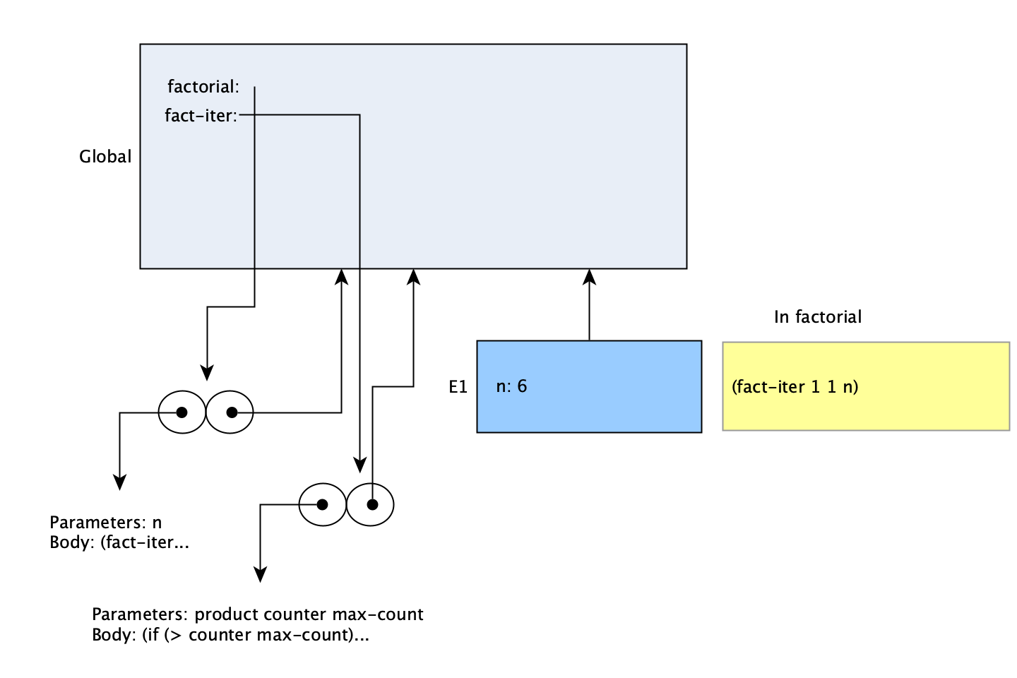
Much like 3.2.2, this is another section with a single exercise involving environment diagrams. There will be a solution file with included code, merely to demonstrate the equivalence of the procedures. There isn’t much to say in advance of the exercises, so I’ll go over in more detail how I’ve drawn my environment diagrams. Here’s an example from the previous section, and I have a few more sample ones below.

The diagrams consist of frames, environment pointers, procedure objects, and my own ‘evaluation’ boxes. Frames are boxes tinted blue, and contain a list of name-value pairs, i.e. ‘bindings’. The environment pointers may be attached to arrows, but are most often just a text label next to a frame. The global environment’s frame is drawn using a larger box (as done in the text), and a lighter tint to show that it’s slightly special as the ‘base’ environment. The evaluation boxes are yellow, and indicate what is being evaluated when the diagram is depicting a particular point in time.
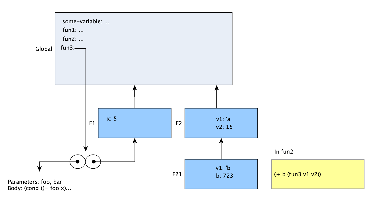
Initially the difference between environments and frames in the diagrams wasn’t entirely clear to me. The distinction is that a frame is a single box that contains variable bindings. The environment is the sequence of frames that can be followed back via pointers (the pointers being represented by arrows). The names of the pointers are also synonymous with the ‘environment’. For example, when referring to Figure 3.1, the text says “environment D” to mean the environment that D points to. As said, I don’t normally use labels on the arrows, or the initial arrow for an environment; the label to the left of a frame marks the start of an environment there, with the pointer being implied. Frames typically do not need to be named; in most cases, the number or name of the environment that begins at that frame can be used. For instance, in the diagram below, ‘Frame 21’ would refer to the box marked by E21. The environment E21 would be the sequence Frame 21 → Frame 2 → Global Frame.

For environment naming, the convention I typically follow is that the environment is assigned a number to distinguish it from others with the same parent, and a new digit is appended for each frame in the chain. This means that it’s usually possible to determine the ‘depth’ of an environment and also know its enclosing environment just from the name. Environment ‘E213’ would likely be the third one created in the first environment of the second environment of the global environment. This doesn’t cover all cases, but the actual names of the environments are not themselves all that important; I just wanted something that could be mostly consistent and easy to come up with. It also has the benefit of suggesting the sequence of frames that makes up an environment.
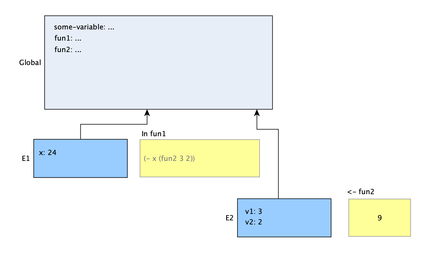
The additional information on my diagrams shows what is in the process of being evaluated. The relevant code is included in a yellow box next to the frame for it. Normally only one line of code will be written there, to indicate the specific line that is being evaluated. The name of the procedure (or a description, for lambdas) will be included as a label above the evaluation box. Frequently, a procedure is in the middle of execution and has called another procedure. In those cases, the code in the box will be slightly grayed out to show that it is not the ‘active’ frame. For a procedure that has completed evaluation, the yellow box will be smaller, and instead of code, the returned value will be shown inside it. The label on top will also use ‘<-’ to show that it is returning from the procedure.
Here’s another example, to clarify what happens with procedure calls. In this one, function fun2 has finished and is returning a value. The other function, fun1 is still in progress as it is awaiting the result of fun2. (Note that this is not meant to be the same functions as the first example.) The definitions for the two procedures are not shown.
